Ashlok Connector Crimping Tutorial
The following outlines how to make your own servo extensions with Ashlok Connectors. This tutorial (and the specialized crimping tool) can also be used to build standard servo extensions, or combination servo extensions (Servo extensions that have one standard connector end and one Ashlok Connector end).
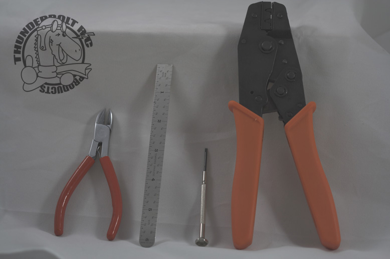
- A specialized crimping tool (This is the most important tool!)
- Wire Striping tool or cutters.
- A small ruler
- Small flat bladed screw driver
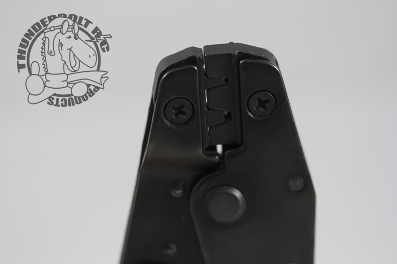
The crimping tool that we sell can be adjusted in several ways. We have found that the crimping tool jaw dies should be setup like the picture on the left. This will make it easy for you to crimp the type of connector pins that are used with standard servo connectors or Ashlok Connectors. The jaw dies can be adjusted by unscrewing the die screw and re-installing the dies according to the picture. Please note: Before tightening the die screws, slowly close the crimper so that both dies align properly, then tighten the die screws.
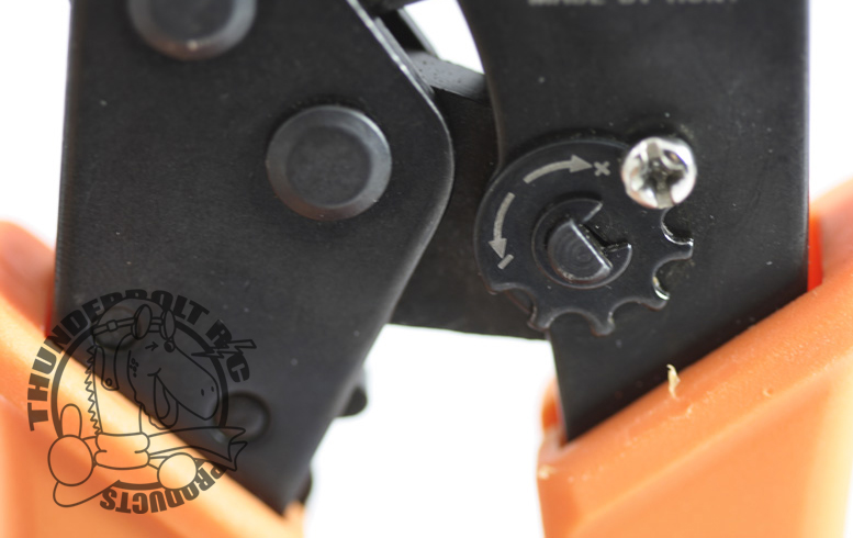
The crimping tool has a slotted disc that is used to adjust the tool tension. This tension adjust determines when the rachet mechanism releases. Depending on which version of the tool you receive, you may have to adjust the tension. In earlier versions of the tool, setting the disc to the "+" side resulted in the jaws releasing sooner (which means less tension), setting the disc to the "-" side results in the jaws releasing later (which means more tension). Later versions of the tool were configured the opposite (because many users were getting confused with the tension setting). With later versions of the tool, setting the tension toward the "+" results in more tension, and setting the tension to "-" results in less tension. You may have to play with this adjustment a bit to determine the proper tension. We found that you should start with the tension disc set to the least amount of tension, and work from there. Different wire, different pins, and especially smaller gauge wire, may require more or less tension. Too much tension can deform and weaken the connector pins, not enough tension will allow the wire to be pulled away from the connector. This may require some trial and error testing depending on the wire and pins that you use.
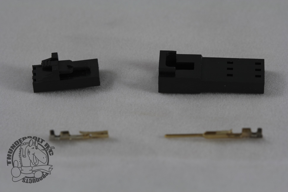
Each Ashlok Connector set is made up of four types of parts. In the picture to the left you can see all of the parts. The top left of the picture shows the Male Connector Housing, the top right shows the Female Connector Housing. The bottom left shows the Female Connector Pin (which works with the Male Connector Housing) and the bottom right shows the Male Connector Pin (which works with the Female Connector Housing).
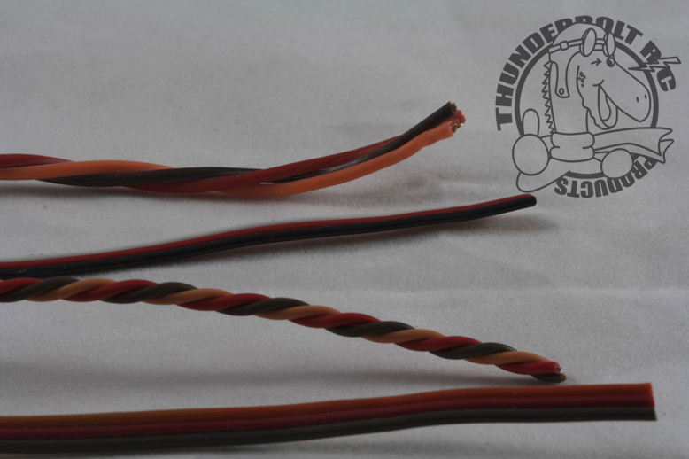
There are many types of servo wire available. In general you should use heavy duty (22AWG) twisted wire. Larger gauge wire will not fit properly into the Ashlok or standard servo connector housings. Twisted wire will reduce radio and electrical interface in your airplane electrical system.
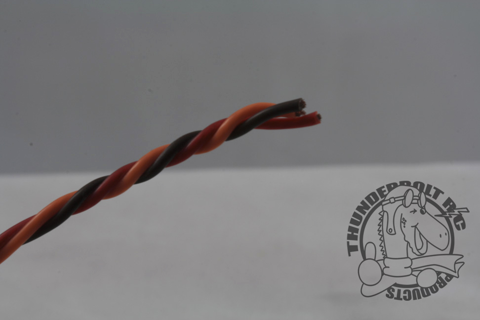
Measure the length of servo wire you need for your application and cut the wire to length. Keep in mind that the Ashlok Connectors are a little longer than the standard servo connectors. It is always best to cut all 3 servo wires with one cut, this way all wires will be the same length.
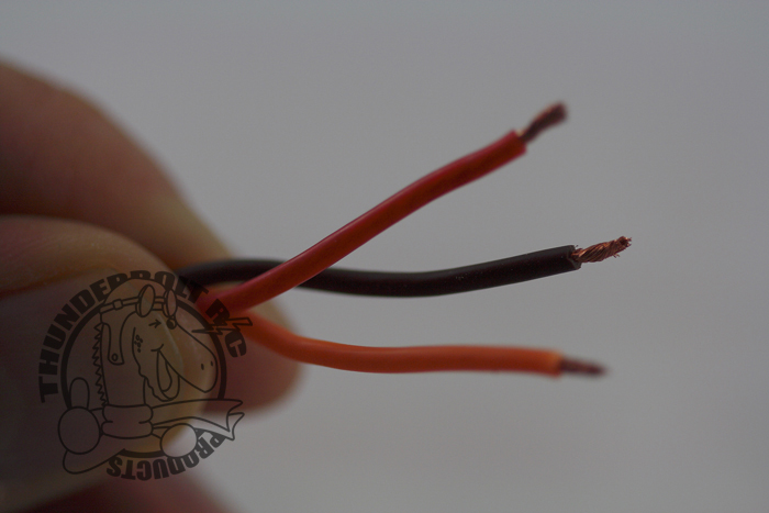
To prepare the wire for crimping, you will need to separate the 3 servo wires by about 1/2". If you are using attached straight wire, you will need to be careful not to cut into the wire insulation. Once the wire is separated, you will need to strip about 1/8" - 3/16" off of each wire.
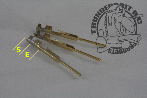
Before crimping, you should take note of how the Connector Pins are configured. From the picture on the left, you can see the Male Connector Pins. Each Connector Pin has 2 sets of "tabs". The first set (denoted by the S section; S stands for "Strain")is designed to crimp around the wire insulation to provide "Strain Relief". The second set (denoted by the E section; E stands for "Electrical")is designed to crimp around the wire strands to provide the "Electrical Connection". Notice the small tabs that stick up on each Connector, these tabs allow the Connector Pin to lock into the Housing. Click on the picture on the left to view closeup pictures of both Male and Female Connector Pins.
The Crimping Tool is designed to crimp both of the Connector Pin crimp areas (The "Strain" area, and the "Electrical" area) in one crimping action. By looking closly at the crimping tool die, you can see that the die is divided into 2 areas. You will have to line up the Connector Pins so that the edge of "E" lines up with left side of the crimping tool die. This will allow each crimp area to be properly crimped.
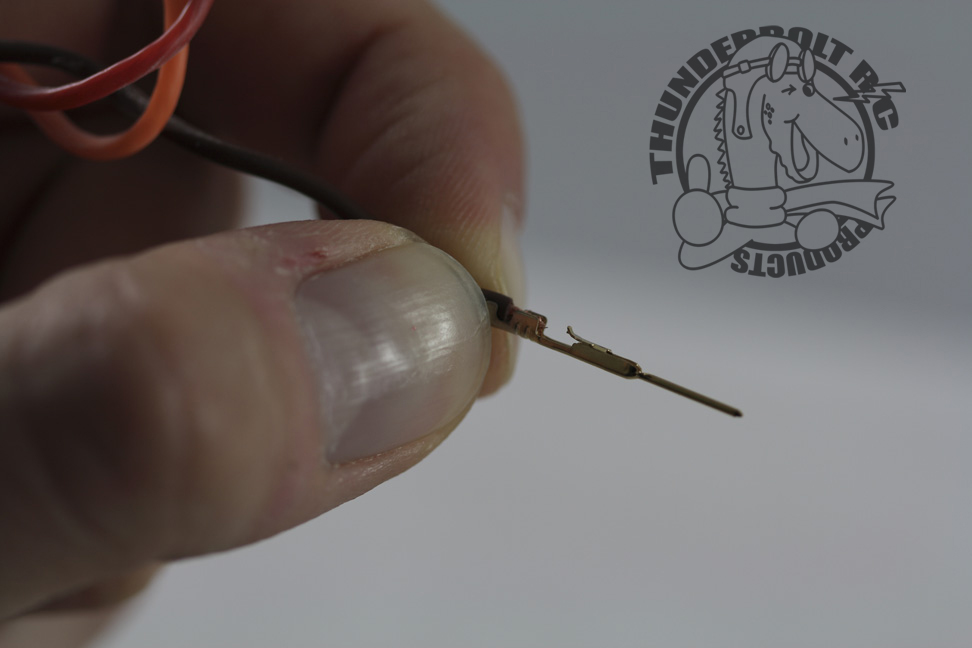
Before crimping the connector to the wire, it is best to pinch the strain relief part of the connector lightly to the wire insulation so the connector stays on the wire while you work with it. This will make it much easier to handle and load into the crimping tool. Use your finger nails to pinch down on the strain relief portion of the connector.
The picture to the right illustrates a wire and connector that are ready for crimping. Notice the positioning of the insulation and wire on the connector.
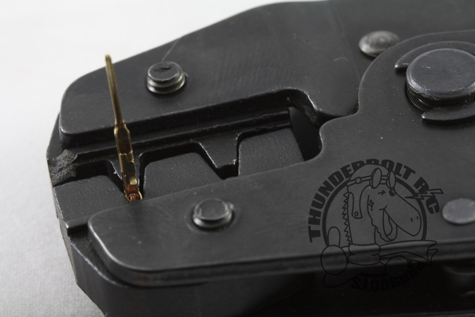
You are now ready to crimp your first pin. Carefully load the Connector Pin into the Crimping Tool jaw as illustrated in the picture to the left. Slowly close the jaws until you hear the first click, making sure the pin stays square to the jaw. With the jaws closed to the first click, you can still reposition the Connector Pin if necessary. Once you are satisfied that the Connector Pin is positioned properly, completely close the jaws until they release. Check the pin, if it crimp areas are not crimped properly or they are deformed, adjust the tension and repeat the instructions above. Make sure the small tab on the Connector Pin is intact. If everything look good, crimp your remaining wires.
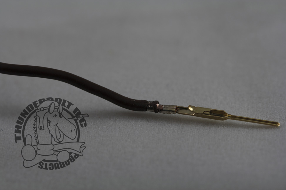
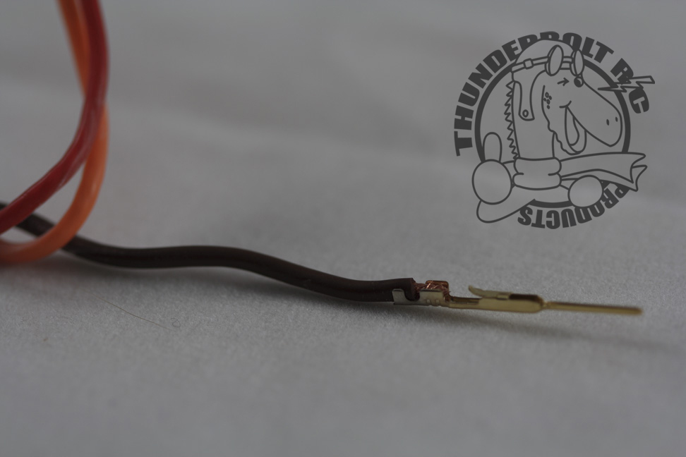
The picture on the right illustrates a successful connector crimp. It is important to check the connector for any deformation (possibly due to the connector moving during crimping or too much pressure being applied by the crimp tool). Also check that the strain relief is tight and providing strain relief for the connector.
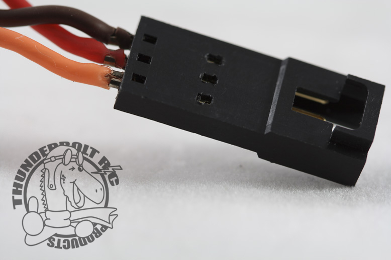
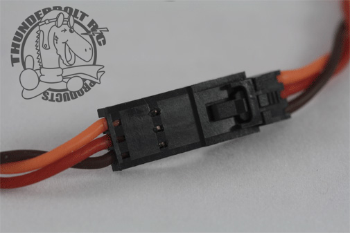
Once you have your set of Connector Pins crimped, you can load them into the Housing. Start by making sure you have the correct sequence of wire (Colours: Generally the sequence goes: Black/Brown - Red - Orange/Yellow/White). Make sure the small locking tab on the Connector Pin is lined up with the small locking hole on the Housing. Gently push each pin into the Housing until it will not go any further. Repeat for the remaining Pins.
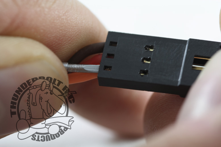
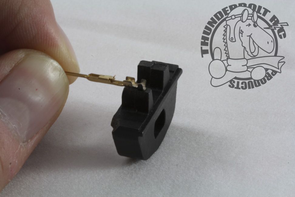
Use the small flat bladed screw driver to push the Connector Pin fully into the Housing. You will see and hear a small click when the locking tab enters the Housing locking hole. Gently pull on the wire to make sure that the Connector Pin is locked. Repeat for the remaining Connector Pins.
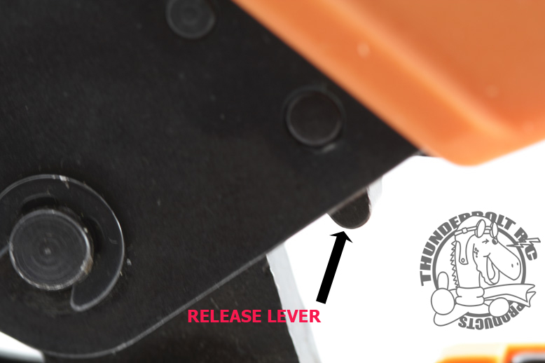
If you have trouble with a crimp, the Crimping Tool has a rachet release lever that will release the jaws. See the picture on the right.
Crimping Tips
- Layout all of your servo extensions before you begin. This is especially important if you plan on using Ashlok Multi-Connectors that will involve more that one servo.
- Measure twice and cut once! Make sure you make your extensions long enough, but not too long. Also leave a little extra just in case you make a crimping mistake.
Visit our Ashlok Product Page (by clicking here) to find everything you need to create reliable servo connections.
Thunderbolt R/C is the official distributor of Ashlok Connectors in Canada. If you have any questions please see the links below or please email us here.